Journal of Automation and Control Research (JACR)
ISSN: 2368-6677

Volume 1, Year 2014 - Pages 38-44
DOI: 10.11159/jacr.2014.005
Learning Robotic Concepts with a 3R Lego NXT Robotic Arm
Michael Thompson1, Victoria M. Serrano R.1, Jordan E. Willem Noriega2, Vanessa Martinez3
1Arizona State University, 1151 S. Forest Ave, Tempe, Arizona
mjthomp3@asu.edu; vmserran@asu.edu
2Arizona State University, School of Sustainable Engineering and the Built Environment, 1151 S. Forest Ave, Tempe, Arizona, 85281
jewillem@asu.edu
3Arizona State University, School of Electrical, Computer, and Energy Engineering, 1151 S. Forest Ave, Tempe, Arizona, 85281
vimartin@asu.edu
Abstract - In this paper we present the use of a 3R Lego robotic arm for teaching basic robotic concepts. The Lego Mindstorms NXT kit is an affordable equipment that can be used to better visualize robotic concepts usually taught in classes. The 3R Lego Robot has 2 degrees of freedom and has been equiped with an accelerometer located at the end-effector to collect acceleration data in the x, y and z axes. Additionally, a gyroscope was placed at the joint for the up and down movement. This allowed for obtaining a plant for the 3R Lego Robot in order to understand the inverse and forward kinematics as well as the physical representation of Denavit-Hartenberg (DH) parameters, velocity manipulability ellipsoids and trajectory planning. This is essential and key in the study of plants that is relevant to everyday use in the industry and academia. This will allow professors at the university to teach more easily with hands-on approach. The Lego product is cost efficient and new programmable blocks can be built and incorporated into Simulink models. Therefore, this can be extended to more complex analysis and feedback control. This will lead to better analysis of the system and provide the students with higher education of what they have learned in class. Furthermore, students will be more competitive to obtain jobs in industry by combining theoretical with experimental approach. Traditionally, industry core concepts are not taught in the class and may be incorporated with the 3R Lego robot for resume building and skill set application. Some papers indicate the use of different programming languages for the Lego Robots; however, none of them have the capabilities and potential of Matlab and Simulink. Additionally, some others have presented simulation work to teach robotic-related concepts, but they either lack the hands-on approach or the hardware utilized is expensive. The importance of this study lies on understanding and implementing basic robotic concepts in Matlab and Simulink together with a 3R Lego robot. Therefore, a more complex Simulink model can be developed for controller design purposes. This paper describes a comparison of a simulation model versus a real life system for helping students to understand modeling system theories versus real world applications.
Keywords: 3R lego robot, Simulink, Matlab, Forward and inverse kinematics, DH parameters, Trajectory planning.
© Copyright 2014 Authors - This is an Open Access article published under the Creative Commons Attribution License terms. Unrestricted use, distribution, and reproduction in any medium are permitted, provided the original work is properly cited.
Date Received: 2014-05-21
Date Accepted: 2014-09-04
Date Published: 2014-10-28
1. Introduction
As technology advances, engineers have always been interested in mimicking animal or human-like behaviors using robots. A great motivation to study robotics is how often they are used in industrial applications. Someone would be hard-pressed to find any factory that does not heavily depend on robots to function. They are faster, more precise, and less expensive in the long run when compared to their human counterparts. Robots are capable of performing a variety of different tasks. In addition, they do not need common safety and comfort requirements that humans need in order to continuously perform them. Furthermore, as long as the robots are intuitively designed, they can be adapted and used in the future for different maneuvers as well. However, understanding how these apparatus work in real life constitute an important component in robotics-related classes. Although robotics concepts are often taught in many books [1], [2], [3], they become hard to visualize in a three-dimensional space. To cope with this problem, some simulating programs have been proposed in the recent years. RoboAnalyzer [4] emerged as an attempt to perform forward kinematics and show animations based on the DH parameters of a KUKA KR5 robot [5]. In a later version, features such as transformations, import of a 3D CAD model and inverse kinematics were also included [6]. Other platforms such as ROBOMOSP [7], RoboWorks [8] and Easy-Rob [9] have been created with the same purpose. In the same matter, a Matlab GUI was developed to simulate and learn the basic concepts of robot dynamics [10]. They include the selection of well-known manipulators like Puma, Stanford and Scara by changing the link masses, inertias and the Denavit-Hartenberg (DH) parameters. The importance on the latter lies on the fact that they are typically used to represent the architecture of a robotic arm and are usually provided by its manufacturer [11]. The DH parameters were used to define different configurations of a FANUC LR Mate 200iB robot and compared to the results provided by an open software for the synthesis, analysis, simulation and control of the same robot [12]. Nonetheless, although they allow to have a better understanding of real physical systems, they become expensive for educational purposes.
Recent studies demonstrate the extended use of Lego NXT kits for educational purposes [13], [14]. While most of them have been used for controller design [15], [16], [17] and signal processing manipulation [18], the number of articles found for teaching basic robotic concepts is lacking. In this matter, a 3 degrees of freedom (DOF) drawing robot has been proposed [19] using Lego NXT and LejOS [20], a program that allowed to have a better resolution for the position of the motor axle compared to the NXT default operating system. Additionally, a robotic arm through the use of Lego Mindstorms NXT kits and the Not Quite C (NQC) language have been developed [21]. Yet, none of them use Matlab and Simulink to study and control the robotic arm; therefore, they limit the research scope that can be developed with the use of Lego NXT kits. Matlab and Simulink constitute a powerful environment that allows the use of toolboxes such as robotics [22], system identification [23], control system tuning [24] and optimization [25] that leads to a better understanding of control systems and robotics.
Our goal is to build and program a robotic arm using critical robotic concepts. This includes forward and inverse kinematic equations, DH parameters, force and velocity manipulability ellipsoids with the use of Simulink and Matlab. The Lego Mindstorms NXT kit allows for a comparison between simulation and real data. This will allow a future integration of more advanced control-related concepts through the use of existent Matlab toolboxes.
2. Methods
In order to control the robot arm to accomplish the task, several analyses were needed including the forward and inverse kinematics, the workspace, trajectory planning and the force and velocity manipulability ellipsoids at the end-effector throughout all the configurations. The manipulator constituted by 4 links (including the base) connected by 3 joints. The aim of forward kinematics is to determine the end-effector position and the orientation as a function of the joint angles. It was illustrated in class that the position and orientation of a body with respect to a reference frame are described by the position vector of the origin and the unit vectors of the frame attached to the body. Hence, with respect to the base frame, the forward kinematics function can be expressed by the homogeneous transformation matrix.
2.1. DH Convention
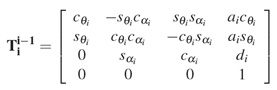
Since the manipulator structure is an open kinematic chain, each joint connects two and only two consecutive links. Therefore, it is reasonable to first describe the kinematic relationship between consecutive links and then to obtain the overall description of the manipulator kinematics in a recursive fashion [1]. To this purpose, the Denavit-Hartenberg (DH) convention was used to construct the direct kinematics function by composition of the individual coordinate transformations expressed by Eq. 1.
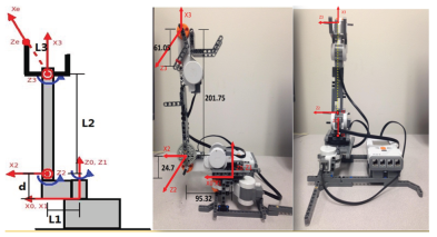
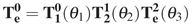
The frame for each link was defined as shown in Fig. 1. Therefore, the coordinate transformation describing the position and orientation of the end-effector frame with respect to the base frame is given by Eq. 2,
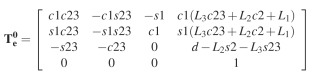
Therefore, the homogeneous transformation matrix for this manipulator is shown below.
Consider the arm in Fig. 1, where the base and the link frames have been illustrated. The axes xi were chosen to minimize the calculation. The DH parameters are specified in the table 1. It is worth pointing out that the frame 3 does not coincide with the end-effector frame and the end-effector frame can differ due to the different tasks.
Table 1. Lego arm D-H parameters
| i | αi | ai | si | θi |
| 1 | 0 | 0 | 0 | 0 |
| 2 | -90° | L1 = 95.32mm | d0 = 24.7mm | θ1 |
| 3 | 0 | L2 = 201.75mm | 0 | θ2 - 90° |
| 4 | 0 | L3 = 61.05mm | 0 | θ3 - 180° |
2.2. Forward Kinematics
If the task is to be specified for the end-effector, it is necessary to assign the end-effector position as a function of time. On the other hand, the joint space denoted the space in the vector of the joint variables (θ1, θ2 and θ3). Accounting for the dependence of position from the joint variables, the forward kinematics equation can be written in the form of Eq. 4 which is obtained from Eq. 3.
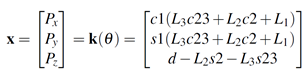
This expression shows three joint space variables that allow specifications of at most three independent operational space variables. On the other hand, the orientation is not a concern, thus all joint angles can be fully defined given a position of the end-effector.
2.3. Inverse Kinematics
The inverse kinematics problem consists of the determination of the joint variables corresponding to a given end-effector position. The solution to this problem is of fundamental importance in order to transform the motion specifications, assigned to the end-effector in the operational space, into the corresponding joint space motions that allow execution of the desired motion. As mentioned above, the manipulator is not a redundant structure, it is easy to compute the closed-form solution for the inverse kinematics based on Eq. 3. Therefore, the solution for the inverse kinematics can be obtained as:

2.4. Workspace
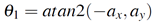
The workspace is the region described by the origin of the end-effector frame when all the manipulator joints execute all possible motions [3]. Since the manipulator has less than 6 degrees of freedom (DOFs), it cannot take any arbitrary position and orientation in space. Therefore, it is necessary to compute its workspace to guarantee all the positions along the path are reachable for the manipulator. In order to simplify the calculation, we chose the end-effector as the center of the third joint and the workspace is shown as Fig. 2a.
Given a set of joint variables, the values of the operational space variables deviate from those computed via direct kinematics and the direct kinematics equation is dependent on the DH parameters by Eq. 4.
2.5. Computation of the Jacobian Matrix
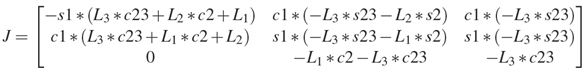
After establishing the relationship between the joint variables and the end-effector position, we are able to compute the differential kinematics to map the joint angle velocities and the end-effector velocities. Therefore, if the end-effector location is expressed with the reference to a minimal representation in the operational space, the Jacobian matrix can be computed via differentiation of the forward kinematics function with respect to the joint variables [1]:
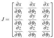
Therefore, we are able to compute the general version of the Jacobian matrix for our Lego arm and the result shows as below:
2.6. Velocity Manipulability Ellipsoids
The evaluation of the manipulator is very helpful for determining suitable manipulator postures to execute a given task in the current configuration. Therefore, it is necessary to compute the velocity manipulability ellipsoids for all the configurations during the task. This allows us to make sure that there are no singular configurations, and more importantly, it can help us to obtain an idea of the capability at the end-effector for all configurations. Consider the set of joint velocities of unit norm [3]:

this equation describes the points on the surface of a sphere in the joint velocity space. Through the differential kinematics equation 4 solved for the joint velocities, we can obtain that:
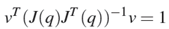
For our Lego arm, since it is a nonredundant manipulator, the points on the surface of the sphere in the joint velocity space are mapped into the points on the surface of the ellipsoid in the end-effector velocity space as shown in Fig. 2b.
2.7. Simulink Programming
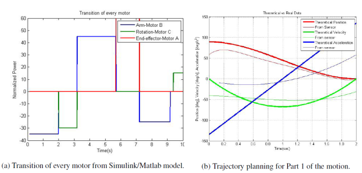
The Simulink model encompasses three motors and six time signals. The motors are connected up and work together in a time sequence in order for the 3R Lego robot to work properly within the desired design specifications. The entire robot ran for approximately 10 seconds allowing each motor to work independently of each other. The motors were actuated at specific time segments so that a smooth path trajectory was accomplished. Three simulated signals of each motor working independent of each other. Three blue signals works together in time to actuate the arm motor. One green signal is actuated to avoid an object during its path. Two red signals are actuated to allow the end-effector to grasp an object and set it back down. The difficult part of programming the motors was to get the motors to work in sequence. After one motor would start the other motor would stop and start. To correct this the global configuration of the motors had to be looked at so that the motors functioned in sequence yet independent of one another as shown in Fig 3a.
2.8. Trajectory Planning
Given an initial configuration and a final assigned posture, we selected a path for the end-effector in the operating space based on workspace and manipulability ellipsoids analysis. We divided the motions into several parts, including (1) reach an object, (2) pick up the object, (3) lift the object, (4) avoid an obstacle, (5) place the object back down and for each part, it lasts approximately 2 seconds. By Eqs. 5, 6, 7, we are able to solve the inverse kinematics for all configurations. The cubic spline trajectory was chosen to plan the point to point motion for each part of the motion. Based on the inverse kinematics, each part of the motion only needs one joint to move which simplifies the calculation. Fig. 3b shows the result for Part 1 of the motion, reaching the object.
The position curve shows that the initial joint angle is 90 degrees and the final joint angle is 0 degrees. The arm starts from rest and end at rest.
2.9. Data Collection
An acceleration sensor was placed at the end-effector and connected to port 1. The sampling rate we set was 0.01 seconds. This allowed the sensor to collect as much information as possible within the ten seconds of running the actual program. This sensor provides acceleration data within the x, y and z axes. The sensor has an orientation so that the axis perpendicular to the floor always shows the Earth's gravitational acceleration. When the sensor is at rest and in the normal horizontal position, the x and y axis will be approximately zero and the z axis will be about 200 counts. This corresponds to a value of 1 g. It was necessary to convert counts to m/s2 in order for the data to coincide with the rest of our calculations. Additionaly, the acceleration in the x, y and z axes was used to calculate the tilt angle with respect to each axis. Then, it was compared to the simulation results from Matlab.
Additionaly, we used a gyroscope to collect the angular velocity of the link of the robotic arm every 0.01 seconds. This gyroscope is capable of measuring the angular velocity with respect to one axis at a time within a range of -360 to 360 degrees. We set it up with with an offset value of 588 to compensate for the discrepancy from the zero degree/sec value when it was at rest. The sensor was placed at the joint that controls the up and down movement of the link. However, since the robotic arm is not very sturdy and the sensor is very sensitive, a post-processing step of the signal was required to smooth it out. Yet, it shows the values collected when the link was even vibrating. A differentiation of the smoothed angular velocity was performed to calculate the angular acceleration of the robotic arm for the first 2 seconds of its trajectory.
3. Results
After a myriad of attempts, we successfully programmed and discovered a worthy process for the 3R Lego robot. The path planned trajectory was designed to specification and allowed for 5 basic steps of the trajectory. This process was tested many times so that the repeatability of the system could be accomplished. The process required that the number of degrees of freedom of the 3R Lego robot be fully utilized in order to pick up an object, avoid an obstacle, and place it back down. Outlined below is a successful process of an iteration of the 3R Lego robot.
The acceleration sensor was used to measure the actual acceleration at the end-effector. The sensor data that was collected shows a linear acceleration at the end-effector for 10 seconds of data collection. As the motors are switching to perform different tasks, the acceleration produces peaks and valleys in acceleration. However, the sensor shows the acceleration due to gravity for the z axis combined with the linear acceleration of the object. One cannot distinguish the actual acceleration in each axis when the sensor is being rotated.
An advantage of having an accelerometer is that it has high accuracy with our applications and is more efficient to calculate the angular position of the end-effector. A big disadvantage is that the sensor may not be sufficient to obtain angular velocity and acceleration.
4. Conclusion
We have shown that a 3R Lego robotic arm can be used to understand basic robotic concepts. A hands-on approach was compared to theoretical results through the use of Matlab and Simulink. An acceleration sensor and a gyroscope were required to obtain the angular distance, and the angular velocity and acceleration, respectively. The use of each sensor have pros and cons that were described in this paper. One way to obtain cleaner velocity and acceleration data would be by the integration of another acceleration sensor along the link to use a differential acceleration process. Having more accurate data is important for the calculation of forward and inverse kinematics that will allow a better control of the robotic arm.
Acknowledgments
The authors of this paper would like thank the Ira A. Fulton Schools of Engineering at Arizona State University for their support and funding of SHPE (Society of Hispanic Professional Engineers) de ASU Robotics. Without their funding, purchasing the Lego Robotics kits that were used would not have been possible and much of the research done could not have been completed.
References
[1] Niku, S. B. (2001). An Introduction to Robotics Analysis, Systems, Applications. NJ: Prentice Hall. View Book
[2] Spong, M., Hutchinson, S. and Vidyasagar, M. (2006). Robot modeling and control. NY: John Wiley & Sons. View Book
[3] Sciavicco, L. and Siciliano, B. (2000). Modelling and control of robot manipulators. NY: Springer. View Book
[4] Rajeevlochana, C.G., and Saha, S.K. (2011). RoboAnalyzer: 3D Model Based Robotic Learning Software. International Conference on Multi Body Dynamics, 3-13. View Article
[5] Rajeevlochana, C. G., Jain, A., Shah, S. V., and Saha, S. K. (2011). Recursive Robot Dynamics in RoboAnalyzer. 15th National Conference on Machines and Mechanisms (NaCoMM), 482-490. View Article
[6] Bahuguna J., Chittawadigi R. G., and Saha, S. K. (2013.) Teaching and Learning of Robot Kinematics Using RoboAnalyzer Software. Advances in Robotics. View Article
[7] Jaramillo-Botero, A., Matta-Gomez, A., Correa-Caicedo, J. F. and Perea-Castro, W. (2006). ROBOMOSP. Robotics & Automation Magazine, IEEE, 13(4), 62-73. View Article
[8] RoboWorks Software. Newtonium Web site. Retrieved from http://www.newtonium.com/. View Article
[9] Easy-ROB3D Software. Easy-ROB Web site. Retrieved from View Article
[10] Toz, M., Kucuk, S. (2010). Dynamics Simulation Toolbox for Industrial Robot Manipulators. Computer Applications in Engineering Education, 18(2), 319-330. View Article
[11] Hayat, A. A., Chittawadigi, R. G., Udai, A. D., and Saha, S. K. (2013). Identification of Denavit-Hartenberg Parameters of an Industrial Robot. AIR'13 Proceedings of Conference on Advances In Robotics, 1-6. View Article
[12] Gonzalez-Palacios M. A., Gonzalez-Barbosa, E. A., Aguilera-Cortes, L. A. (2013). SnAM: a simulation software on serial manipulators. Engineering with Computers, 29, 87-94. View Article
[13] Behrens et al. (2010). MATLAB Meets LEGO Mindstorms-A Freshman Introduction Course Into Practical Engineering. IEEE Trans. on Education, 53(2), 306-317. View Article
[14] Green, A. (2013). LEGO Robotics in STEM Education. D&T Practice, 1, 22-24. View Article
[15] A. Cruz-Martin et al. (2012). A LEGO Mindstorms NXT approach for teaching at Data Acquisition, Control Systems Engineering and Real-Time Systems undergraduate courses. Computers and Education, 59, 974-988. View Article
[16] Y. Kim. (2011). Control Systems Lab Using a LEGO Mindstorms NXT Motor System. IEEE Trans. on Education, 54(3), 452-461. View Article
[17] A. Valera et al. (2011). Design and Implementation of Kalman Filters applied to Lego NXT based Robots. Preprints of the 18th IFAC World Congress, 9830-9835. View Article
[18] Ferri, B. H. et al. (2009). Signal Processing Experiments with the LEGO MINDSTORMS NXT Kit for Use in Signal and Systems Courses. American Control Conference, 3787-3792. View Article
[19] Hamori, A., Lengyel, J. and Resko, B. (2011). 3DOF drawing robot using LEGO-NXT. 15th International Conference on Intelligent Engineering Systems (INES), 293-295. View Article
[20] Moral, J. A. B. (2009). Develop lejos programs step by step. Retrieved from www.juanantonio.info/. View Article
[21] Nee, Y. Y. (2007). ROBOTIC ARM SYSTEM BY USING LEGO MINDSTORMS (Unpublished dissertation). Universiti Teknikal Malaysia Melaka, Malaysia.
[22] Corke, P.I. (2011). Robotics, Vision & Control. Springer. View Book
[23] Ljung, L. (1999). System Identification, Theory for the User. NJ: Prentice Hall. View Book
[24] Golnaraghi, F., Kuo, B. C. (2009). Automatic Control Systems. NY: WILEY. View Book
[25] Nocedal, J., Wrigth, S. (2006). Numerical Optimization. NY: Springer. View Book